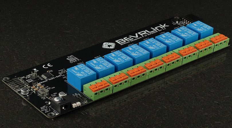
For this tutorial we have connected a Raspberry Pi 5 to the BEVRLink Raspberry Pi 5 8 Channel Relay 12V. With this relay module board you need the BEVRLink Power Supply 12V 2A.
This guide works for BEVRLink Raspberry Pi 5 4 Channel Relay, just omit the relay 5-8 and the status LED from the code. With this relay module you can either power the Raspberry Pi directly or back feed it from a connected BEVRLink relay module through the Expansion Connector.
Optional for a safe setup we recommend to use case for both the manager and relay boards: BEVRLink Cases
Introduction
Welcome to our comprehensive guide on getting started with C++ using the BEVRLink 4/8-Channel Relay Hat for Raspberry Pi. This guide includes instructions for controlling the relays via GPIO pins and I2C support for the BEVRLink 8 channel and 4 channel relays. This setup allows you to control multiple devices through your Raspberry Pi efficiently.
What You'll Need
- Raspberry Pi (any model with GPIO pins)
- BEVRLink 4/8-Channel Relay Hat
- BEVRLink 4 or 8 channel boards
- Basic understanding of C++ programming
- WiringPi library and i2c-tools installed on your Raspberry Pi
Understanding the Pinout
Here’s a detailed pinout table for the BEVRLink relay hat:
| Relay Channel | RPI Pin Number | BCM Pin | Description |
|---|---|---|---|
| Channel 1 | 29 | 5 | 4 & 8 ch HAT |
| Channel 2 | 31 | 6 | 4 & 8 ch HAT |
| Channel 3 | 33 | 13 | 4 & 8 ch HAT |
| Channel 4 | 36 | 16 | 4 & 8 ch HAT |
| Channel 5 | 35 | 19 | 8 ch HAT |
| Channel 6 | 38 | 20 | 8 ch HAT |
| Channel 7 | 40 | 21 | 8 ch HAT |
| Channel 8 | 37 | 26 | 8 ch HAT |
| Status LED | 32 | 12 | Status LED |
Setting Up the Hardware
-
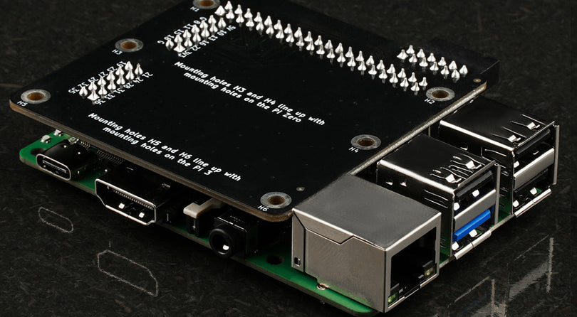
Connect the Relay Hat to Your Raspberry Pi: Carefully align the BEVRLink Relay Hat with the GPIO pins on your Raspberry Pi and press it down firmly to ensure a good connection.
-
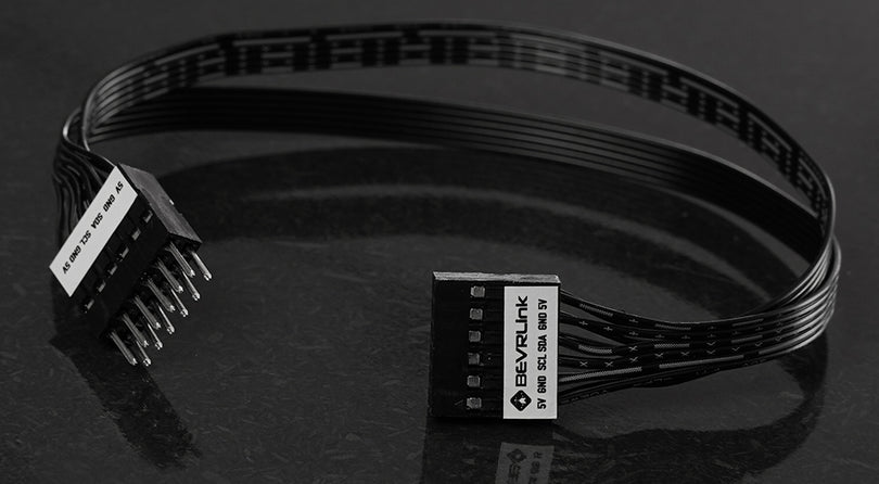
Connect the additional boards: Connect the additonal boards using the BEVRLink Expander connector.
-
Power Up Your Raspberry Pi: Connect your Raspberry Pi to a power source and let it boot up.
Installing Required Tools
Ensure you have WiringPi and i2c-tools installed:
sudo apt-get update
sudo apt-get install wiringpi i2c-tools
Writing Your C++ Program
Below is a comprehensive C++ program that can control the relays using GPIO, MCP23008, or PCA9554 via I2C.
#include <wiringPi.h>
#include <wiringPiI2C.h>
#include <iostream>
#include <unistd.h>

#define MCP23008_ADDRESS 0x20 // Adjust the address based on your configuration
#define PCA9554_ADDRESS 0x38  // Adjust the address based on your configuration

#define IODIR 0x00
#define GPIO_REG  0x09  // Renamed to avoid conflict
#define OLAT  0x0A
#define CONFIG 0x03
#define OUTPUT_PORT 0x01

const int gpio_channels[] = {5, 6, 13, 16, 19, 20, 21, 26};  // BCM pins for GPIO relay channels

enum ControlMethod {
    GPIO_METHOD,
    MCP23008_METHOD,
    PCA9554_METHOD
};

void setupGPIO() {
    wiringPiSetupGpio();  // Initialize WiringPi using BCM pin numbers
    for(int i = 0; i < 8; i++) {
        pinMode(gpio_channels[i], OUTPUT);
        digitalWrite(gpio_channels[i], HIGH);  // Initialize all relays to off
    }
}

void toggleGPIORelay(int channel) {
    digitalWrite(gpio_channels[channel], LOW);  // Turn relay on
    sleep(1);                    // Wait for 1 second
    digitalWrite(gpio_channels[channel], HIGH); // Turn relay off
}

void setupMCP23008(int fd) {
    wiringPiI2CWriteReg8(fd, IODIR, 0x00); // Set all GPIO pins as outputs
    wiringPiI2CWriteReg8(fd, OLAT, 0xFF); // Set all outputs to HIGH (relays off)
}

void toggleMCP23008Relay(int fd, int channel) {
    uint8_t state = wiringPiI2CReadReg8(fd, OLAT);
    state &= ~(1 << channel);  // Set the relay pin to LOW
    wiringPiI2CWriteReg8(fd, OLAT, state);
    sleep(1); // Wait for 1 second
    state |= (1 << channel);  // Set the relay pin to HIGH
    wiringPiI2CWriteReg8(fd, OLAT, state);
}

void setupPCA9554(int fd) {
    wiringPiI2CWriteReg8(fd, CONFIG, 0x00); // Set all GPIO pins as outputs
    wiringPiI2CWriteReg8(fd, OUTPUT_PORT, 0xFF); // Set all outputs to HIGH (relays off)
}

void togglePCA9554Relay(int fd, int channel) {
    uint8_t state = wiringPiI2CReadReg8(fd, OUTPUT_PORT);
    state &= ~(1 << channel);  // Set the relay pin to LOW
    wiringPiI2CWriteReg8(fd, OUTPUT_PORT, state);
    sleep(1); // Wait for 1 second
    state |= (1 << channel);  // Set the relay pin to HIGH
    wiringPiI2CWriteReg8(fd, OUTPUT_PORT, state);
}

int main(int argc, char *argv[]) {
    if (argc < 2) {
        std::cerr << "Usage: " << argv[0] << " <method> (gpio, mcp23008, pca9554)" << std::endl;
        return -1;
    }

    std::string method_str = argv[1];
    ControlMethod method;
    int fd = -1;

    if (method_str == "gpio") {
        method = GPIO_METHOD;
        setupGPIO();
    } else if (method_str == "mcp23008") {
        method = MCP23008_METHOD;
        fd = wiringPiI2CSetup(MCP23008_ADDRESS);
        if (fd == -1) {
            std::cerr << "Failed to initialize I2C for MCP23008" << std::endl;
            return -1;
        }
        setupMCP23008(fd);
    } else if (method_str == "pca9554") {
        method = PCA9554_METHOD;
        fd = wiringPiI2CSetup(PCA9554_ADDRESS);
        if (fd == -1) {
            std::cerr << "Failed to initialize I2C for PCA9554" << std::endl;
            return -1;
        }
        setupPCA9554(fd);
    } else {
        std::cerr << "Invalid method. Use gpio, mcp23008, or pca9554" << std::endl;
        return -1;
    }

    std::cout << "Starting Relay Control using " << method_str << "..." << std::endl;

    for(int i = 0; i < 8; i++) {
        std::cout << "Toggling Relay " << i+1 << std::endl;
        if (method == GPIO_METHOD) {
            toggleGPIORelay(i);
        } else if (method == MCP23008_METHOD) {
            toggleMCP23008Relay(fd, i);
        } else if (method == PCA9554_METHOD) {
            togglePCA9554Relay(fd, i);
        }
    }

    std::cout << "Relay Control Finished." << std::endl;
    return 0;
}
Running Your Program
-
Save your C++ program as
relay_control.cpp. -
Compile the program using g++:
g++ -o relay_control relay_control.cpp -lwiringPi -
Run the program with the appropriate method argument:
sudo ./relay_control gpio
sudo ./relay_control mcp23008
sudo ./relay_control pca9554
You should see each relay toggle on and off in sequence, with a one-second delay between each action.
Conclusion
Congratulations! You've successfully set up your BEVRLink 4/8-Channel Relay Hat with support for GPIO, MCP23008, and PCA9554 using C++. This versatile setup allows you to control multiple devices through your Raspberry Pi, making it perfect for complex projects such as home automation systems, industrial controls, and more. Experiment with different configurations and integrate more complex logic into your C++ programs to take full advantage of your relay hat and BEVRLink boards.
Stay tuned for more tutorials and project ideas. Happy coding!

