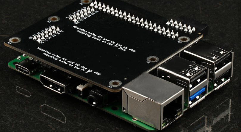
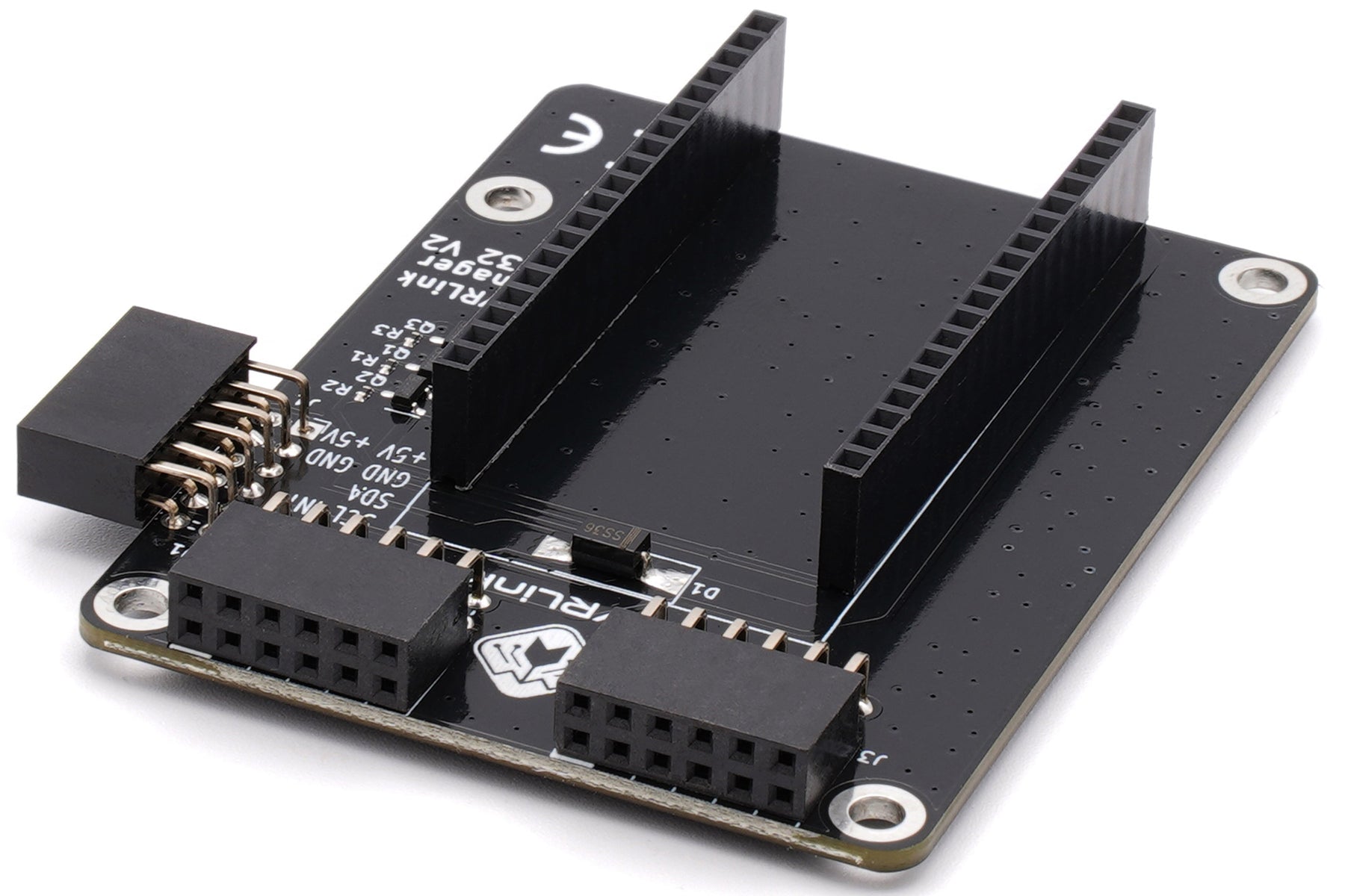
The pinout described below is referencing the module numbering of the module used. The position is from the outside view when you are looking at the connector.
GPIO 1, left
ESP8266
| 5V | D10 | D7 | D5 | D3 | 3V3 |
| GND | D9 | D6 | D4 | A0 | GND |
ESP32
|
5V |
35 |
33 |
31 |
29 |
3V3 |
| GND |
34 |
32 |
30 |
28 |
GND |
Pico
|
5V |
11 |
14 |
16 |
19 |
3V3 |
| GND |
12 |
15 |
17 |
20 |
GND |
GPIO 2, right
ESP32
|
3 |
5 |
7 |
9 |
11 |
13 |
|
4 |
6 |
8 |
10 |
12 |
GND |
Pico
|
21 |
24 |
26 |
29 |
32 |
35 |
|
22 |
25 |
27 |
31 |
34 |
GND |
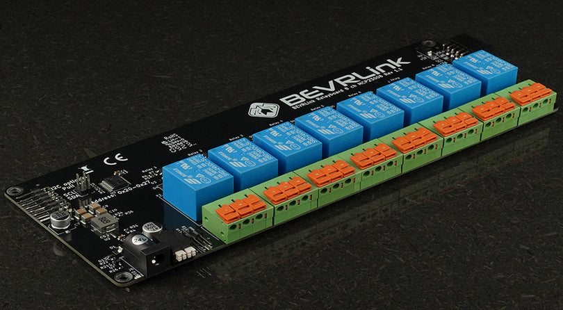
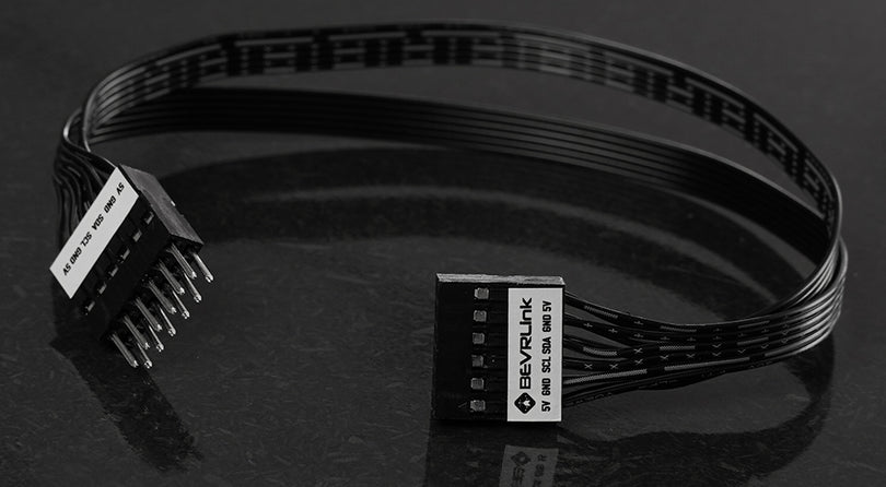
Output connector
Connect to the relay

Looking at the connector
|
5V |
GND |
SDA |
SCL |
GND |
5V |
| 5V |
GND |
- |
INT |
GND |
5V |