Welcome to our guide on getting started with Node-RED using the BEVRLink 4/8-Channel Relay HAT for Raspberry Pi!
This tutorial will walk you through the process of setting up and configuring your Raspberry Pi to control relays using Node-RED, making it perfect for home automation projects, IoT applications, and more.
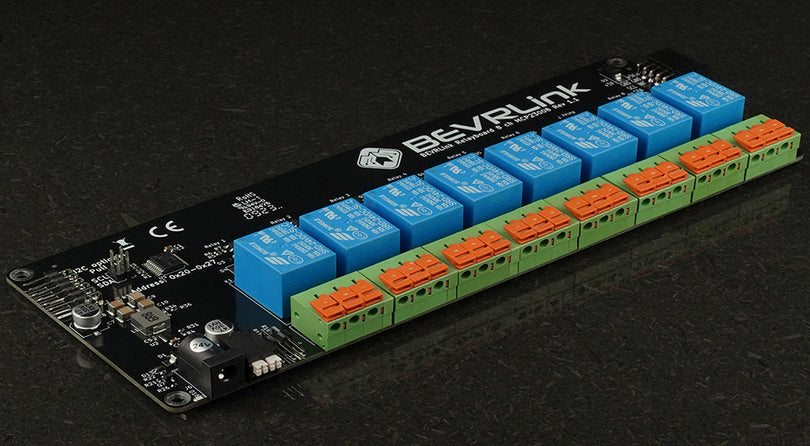
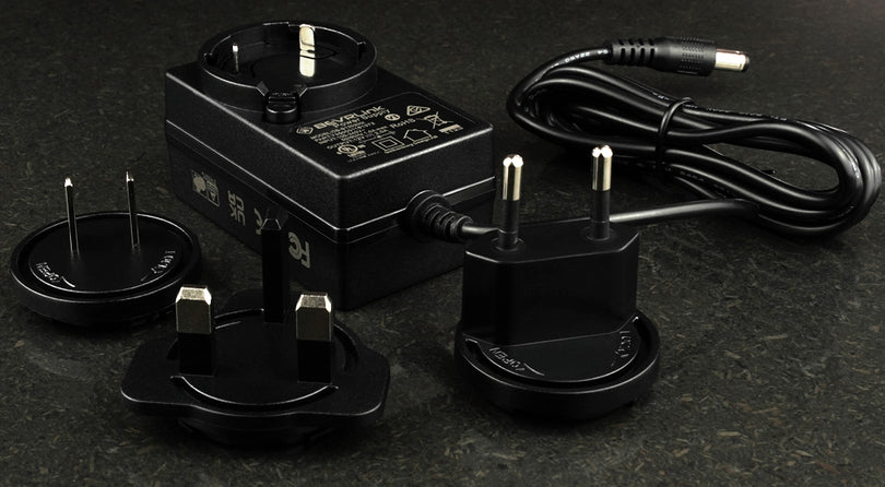
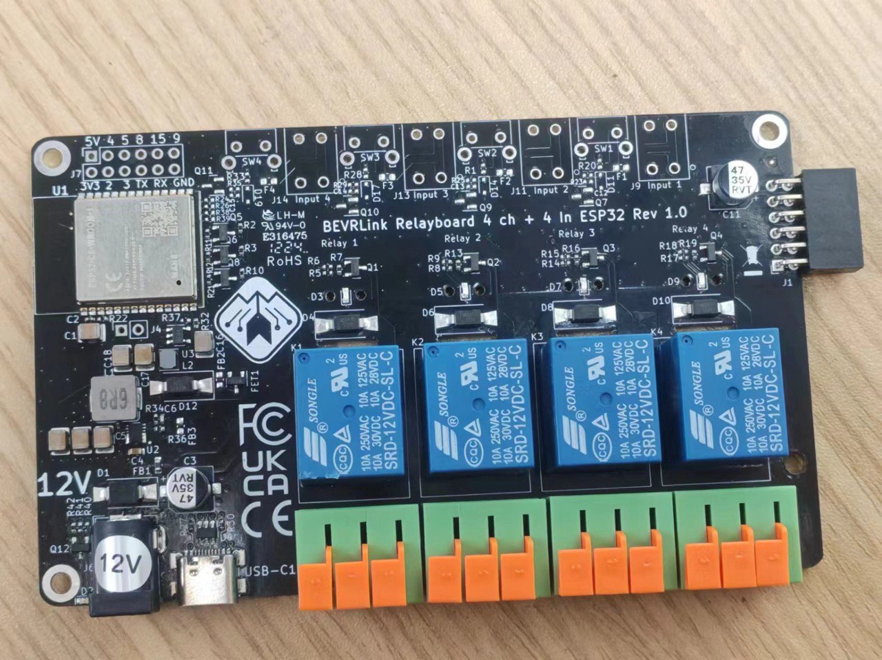
For this we have connected a Raspberry Pi 5 to the BEVRLink Raspberry Pi 5 8 Channel Relay 12V. With this relay module board you need the BEVRLink Power Supply 12V 2A.
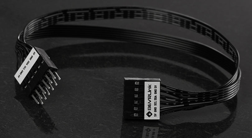
This guide works for BEVRLink Raspberry Pi 5 4 Channel Relay, just omit the relay 5-8 and the status LED from the code. With this relay module you can either power the Raspberry Pi directly or back feed it from a connected BEVRLink relay Module through the Expansion Connector.
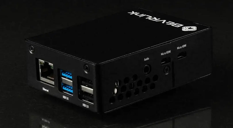
Optional for a safe setup we recommend to use case for both the manager and relay boards: BEVRLink Cases
What You Will Need
- Raspberry Pi (any model with GPIO pins)
- BEVRLink 4/8-Channel Relay HAT
- MicroSD card (16GB or larger) with Raspberry Pi OS installed
- Power supply for the Raspberry Pi
- Internet connection
- Node-RED installed on your Raspberry Pi
Pinout Configuration
Here’s the pinout configuration for connecting the BEVRLink Relay HAT to your Raspberry Pi:
| Relay Channel | RPI Pin Number | BCM Pin | Description |
|---|---|---|---|
| Channel 1 | 29 | 5 | 4 & 8 ch HAT |
| Channel 2 | 31 | 6 | 4 & 8 ch HAT |
| Channel 3 | 33 | 13 | 4 & 8 ch HAT |
| Channel 4 | 36 | 16 | 4 & 8 ch HAT |
| Channel 5 | 35 | 19 | 8 ch HAT |
| Channel 6 | 38 | 20 | 8 ch HAT |
| Channel 7 | 40 | 21 | 8 ch HAT |
| Channel 8 | 37 | 26 | 8 ch HAT |
| Status LED | 32 | 12 | Status LED |
Additionally, more relays can be connected using I2C expanders, allowing for efficient control and communication with multiple relays.
Step-by-Step Guide
1. Set Up Your Raspberry Pi
If you haven’t already, set up your Raspberry Pi by following these steps:
- Download and install Raspberry Pi OS on your microSD card.
Enable SSH
To enable SSH, you need to place an empty file named ssh (without any extension) into the boot partition of your microSD card. Here’s how:
- Insert the microSD card into your computer.
- Open the boot partition (it should be labeled
bootor similar). - Create a new empty file and name it
ssh(make sure there is no file extension). - Safely eject the microSD card and insert it into your Raspberry Pi.
Connect to Your Raspberry Pi via SSH
- Power up your Raspberry Pi and connect it to your network (via Ethernet or Wi-Fi).
- Find the IP address of your Raspberry Pi. You can do this by checking your router’s connected devices list or using a network scanning tool like
nmap. - Open a terminal on your computer and connect to your Raspberry Pi using SSH:
ssh pi@<your_pi_ip_address> - When prompted, enter the default password (
raspberry), or the password you set during setup.
2. Install Node-RED
To install Node-RED, open a terminal on your Raspberry Pi (via SSH) and run the following commands:
bash <(curl -sL https://raw.githubusercontent.com/node-red/linux-installers/master/deb/update-nodejs-and-nodered)
This script will install Node-RED and Node.js on your Raspberry Pi. Once installed, you can start Node-RED by running:
node-red-start
Access Node-RED in your browser by navigating to http://<your_pi_ip_address>:1880.
3. Configure GPIO in Node-RED
Node-RED provides a powerful interface to control the GPIO pins on your Raspberry Pi. To get started, follow these steps:
- Open Node-RED in your browser.
- Go to the menu (three horizontal bars) and select
Manage palette. - Search for the
node-red-node-pi-gpiopackage and install it.
4. Connect the Relay HAT
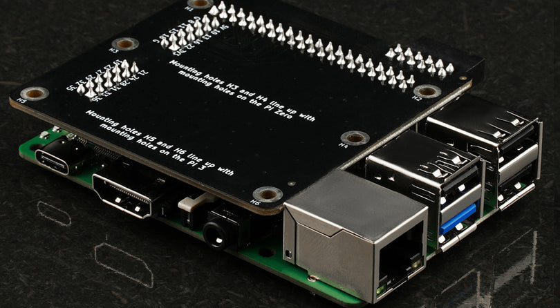
Carefully place the BEVRLink Relay HAT onto the GPIO pins of your Raspberry Pi, ensuring that the pins align correctly.
5. Create Your First Flow
With Node-RED, you can create flows to control your relays. Here’s a simple example to turn on Relay Channel 1:
- Drag an
injectnode (found under the input category) to the workspace. - Drag a
rpi gpio outnode (found under the raspberry pi category) to the workspace. - Connect the
injectnode to therpi gpio outnode. - Double-click the
rpi gpio outnode and configure it:- Select GPIO5 (corresponding to RPI Pin 29, BCM Pin 5).
- Set the
TypetoDigital Output. - Set the
Initial statetoLow(0). - Set the
PayloadtoHigh(1) to turn on the relay.
- Deploy your flow and test it by clicking the inject button.
6. Control I2C Connected Relays
To control additional relays connected via I2C expanders, you need to install the appropriate Node-RED nodes for I2C communication. Follow these steps:
-
Install the I2C nodes by opening the Node-RED palette manager:
- Go to the menu (three horizontal bars) and select
Manage palette. - Search for
node-red-contrib-i2cand install it.
- Go to the menu (three horizontal bars) and select
-
Connect your I2C expander and identify its I2C address. You can use the
i2cdetecttool in the terminal:sudo apt-get install -y i2c-tools sudo i2cdetect -y 1 -
Create a flow to control the I2C relays:
- Drag an
injectnode to the workspace. - Double-click the
injectnode to configure it:-
Name: Set a descriptive name for the action (e.g.,
Configure Relay 4 ch Outputs). -
Payload: Set the payload to the desired buffer values (e.g.,
Buffer [3, 0]). -
Payload Type: Choose
bufferfrom the dropdown menu.
-
Name: Set a descriptive name for the action (e.g.,
- Drag an
i2c outnode to the workspace. - Connect the
injectnode to thei2c outnode. - Double-click the
i2c outnode and configure it:- Set the
I2C addressto the address of your expander. - Set the
Busto1(if using the default I2C bus). - Set the
Send bytesto2.
- Set the
- Drag an
Configuration Details
| Expander | Description | I2C Address | Command Byte | Data Byte |
|---|---|---|---|---|
| Relay 4 ch | PCA9554 | 56 | 3 (Config) | 0 (All outputs) |
| Relay 8 ch | MCP23008 | 32 | 0 (IODIR) | 0 (All outputs) |
- Deploy your flow and test it by clicking the inject button.
Conclusion
Controlling relays with Node-RED and the BEVRLink Relay HAT opens up a world of possibilities for your Raspberry Pi projects. Whether you’re automating your home, building smart devices, or experimenting with IoT, this setup provides a versatile and powerful platform. Adding I2C expanders allows for even more relays to be controlled efficiently.
We hope this guide helps you get started with your Node-RED and Raspberry Pi relay control project. If you have any questions or need further assistance, feel free to reach out to our support team. Happy tinkering!
Example Flow Configuration
Relay 4 ch (PCA9554)
-
Inject Node:
-
Name:
Configure Relay 4 ch Outputs -
Payload:
Buffer [3, 0] -
Payload Type:
buffer
-
Name:
-
I2C Out Node:
-
Name:
Relay 4 ch I2C Out -
Bus:
1 -
Address:
56 -
Send bytes:
2
-
Name:
Connect the inject node to the i2c out node.
Turn On Relay Channel 1 for Relay 4 ch
-
Inject Node:
-
Name:
Turn On Relay 4 ch Channel 1 -
Payload:
Buffer [1, 1] -
Payload Type:
buffer
-
Name:
-
I2C Out Node:
-
Bus:
1 -
Address:
56 -
Send bytes:
2
-
Bus:
Turn Off Relay Channel 1 for Relay 4 ch
-
Inject Node:
-
Name:
Turn Off Relay 4 ch Channel 1 -
Payload:
Buffer [1, 0] -
Payload Type:
buffer
-
Name:
-
I2C Out Node:
-
Bus:
1 -
Address:
56 -
Send bytes:
2
-
Bus:
Relay 8 ch (MCP23008)
-
Inject Node:
-
Name:
Configure Relay 8 ch Outputs -
Payload:
Buffer [0, 0](to set all pins as outputs) -
Payload Type:
buffer
-
Name:
-
I2C Out Node:
-
Name:
Relay 8 ch I2C Out -
Bus:
1 -
Address:
32 -
Send bytes:
2
-
Name:
Connect the inject node to the i2c out node.
Turn On Relay Channel 1 for Relay 8 ch
-
Inject Node:
-
Name:
Turn On Relay 8 ch Channel 1 -
Payload:
Buffer [9, 1](9 is the GPIO register address) -
Payload Type:
buffer
-
Name:
-
I2C Out Node:
-
Bus:
1 -
Address:
32 -
Send bytes:
2
-
Bus:
Turn Off Relay Channel 1 for Relay 8 ch
-
Inject Node:
-
Name:
Turn Off Relay 8 ch Channel 1 -
Payload:
Buffer [9, 0](9 is the GPIO register address) -
Payload Type:
buffer
-
Name:
-
I2C Out Node:
-
Bus:
1 -
Address:
32 -
Send bytes:
2
-
Bus:
Using GPIO Nodes to Control Relays
In addition to using the I2C nodes, you can also control the relays via GPIO nodes in Node-RED.
Example GPIO Flow Configuration
-
Inject Node:
-
Name:
Turn On Relay GPIO -
Payload:
1 -
Payload Type:
num
-
Name:
-
GPIO Out Node:
- Pin: The GPIO pin number corresponding to the relay channel.
-
Name:
Relay GPIO Out -
Type:
Digital Output -
Initial Level:
Low
Connect the inject node to the GPIO out node.
Turn Off Relay GPIO
-
Inject Node:
-
Name:
Turn Off Relay GPIO -
Payload:
0 -
Payload Type:
num
-
Name:
-
GPIO Out Node:
- Pin: The GPIO pin number corresponding to the relay channel.
-
Name:
Relay GPIO Out -
Type:
Digital Output -
Initial Level:
Low
Deploy and Test
- Deploy the Flow in Node-RED.
-
Trigger the Inject Nodes:
- Trigger
Configure Relay 4 ch Outputsfirst. - Trigger
Turn On Relay 4 ch Channel 1. - Trigger
Turn Off Relay 4 ch Channel 1. - Similarly, test the Relay 8 ch configuration.
- Trigger
Turn On Relay GPIO. - Trigger
Turn Off Relay GPIO.
- Trigger
This setup ensures the PCA9554 and MCP23008 are configured, and the relay channels can be controlled via Node-RED. If you encounter any issues, double-check the configurations and connections.

