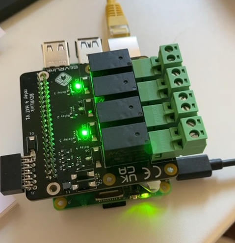


What is the BEVRLink Relay 4 with ESP32?
Imagine you have a magic switch that can turn things on and off using your phone or a button. The BEVRLink Relay 4 with inbuilt ESP32 12V is exactly that! It features four relays that let you control lights, fans, or other gadgets, and it includes an ESP32-C6 module with Wi-Fi, Bluetooth, and Zigbee/Matter support for wireless control.
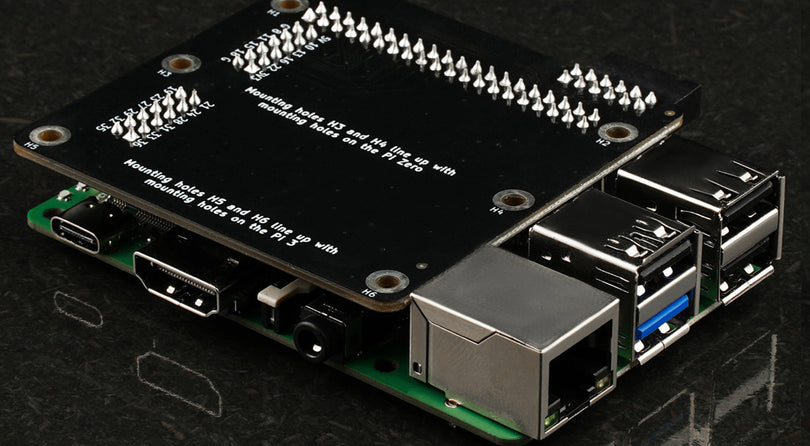
To power the board, you’ll need the BEVRLink Power Supply 12V 2A. For a safe setup, we recommend using BEVRLink Cases for both the relay and manager boards.
The example below is just one way to set up the relay module, demonstrating control with and without buttons. We’ll provide code to control the relays, which you can later expand to include wireless control via Wi-Fi or Bluetooth.
What You Need to Get Started:
- BEVRLink Relay 4 with ESP32 – The main controller.
- 12V Power Supply – Required to power both the relays and the ESP32 (after programming).
- USB Cable – Used only for programming (not required afterward).
- Arduino IDE – A free program to write and send code.
Step 1: Set Up Your Computer
You'll need to install Arduino IDE, which is a simple program for writing code:
- Download & Install Arduino IDE from arduino.cc.
-
Add ESP32 Support:
- Open Arduino IDE.
- Click File > Preferences.
- Copy this link and paste it under "Additional Boards Manager URLs":
https://espressif.github.io/arduino-esp32/package_esp32_index.json - Click OK.
- Now go to Tools > Board > Boards Manager.
- Search for ESP32 and install the package from Espressif Systems.
- Select ESP32C6 Dev Module under Tools > Board.

Step 2: Connect the Hardware
Your board has four relays (R1 to R4), which act as switches. It also has four buttons (B1 to B4) to manually turn things on/off.
- Relays (R1–R4): These control the electrical devices.
- Buttons (B1–B4): Press these to manually switch relays on/off.
- SDA & SCL Pins: These allow communication with other smart devices.
-
Power Supply:
- The USB cable is only needed for programming.
- Once programmed, the 12V power supply will power both the ESP32 and the relays.
Pinout

Step 3: Write Your First Code!
This simple code turns the relays on and off every second.
#include <Wire.h>

// Define relay pins
#define R1 10
#define R2 11
#define R3 22
#define R4 23

void setup() {
  pinMode(R1, OUTPUT);
  pinMode(R2, OUTPUT);
  pinMode(R3, OUTPUT);
  pinMode(R4, OUTPUT);
}

void loop() {
  digitalWrite(R1, HIGH);
  digitalWrite(R2, HIGH);
  digitalWrite(R3, HIGH);
  digitalWrite(R4, HIGH);
  delay(1000);  // Wait 1 second

  digitalWrite(R1, LOW);
  digitalWrite(R2, LOW);
  digitalWrite(R3, LOW);
  digitalWrite(R4, LOW);
  delay(1000);  // Wait 1 second
}
Step 4: Upload Your Code
- Connect your BEVRLink Relay 4 to your computer with a USB cable.
- In Arduino IDE, select Tools > Port, then pick your board.
- Click the upload button (→) to send the code.
Step 5: Power It Properly!
- If you're just uploading code, the USB cable is enough to power the ESP32.
- If you want the relays to actually switch devices, you must connect a 12V power supply.
- After programming, you no longer need the USB cable – the 12V power supply will power both the ESP32 and the relays.
Step 6: Test It!
Once uploaded, your relays should turn on and off every second. 🎉 Try connecting a small LED or fan to see it in action!
Step 7: Controlling the Relays Over Wi-Fi
Now, let's make the relays controllable over Wi-Fi using a simple web interface.
1. Install the Required Libraries
In Arduino IDE, go to Sketch > Include Library > Manage Libraries, then search for and install:
- WiFi (built into ESP32)
- WebServer
2. Upload This Wi-Fi Control Code
This code creates a simple webpage that lets you turn each relay ON or OFF using your browser.
#include <WiFi.h>
#include <WebServer.h>

// Wi-Fi credentials
const char* ssid = "YOUR_WIFI_NAME";
const char* password = "YOUR_WIFI_PASSWORD";

// Create a web server on port 80
WebServer server(80);

// Relay pins
#define R1 10
#define R2 11
#define R3 22
#define R4 23

void handleRoot() {
  String html = "<html><body><h2>Relay Control</h2>";
  html += "<p><a href='/relay1on'>Relay 1 ON</a> | <a href='/relay1off'>Relay 1 OFF</a></p>";
  html += "<p><a href='/relay2on'>Relay 2 ON</a> | <a href='/relay2off'>Relay 2 OFF</a></p>";
  html += "<p><a href='/relay3on'>Relay 3 ON</a> | <a href='/relay3off'>Relay 3 OFF</a></p>";
  html += "<p><a href='/relay4on'>Relay 4 ON</a> | <a href='/relay4off'>Relay 4 OFF</a></p>";
  html += "</body></html>";
  server.send(200, "text/html", html);
}

void setup() {
  Serial.begin(115200);

  pinMode(R1, OUTPUT);
  pinMode(R2, OUTPUT);
  pinMode(R3, OUTPUT);
  pinMode(R4, OUTPUT);

  // Connect to Wi-Fi
  WiFi.begin(ssid, password);
  while (WiFi.status() != WL_CONNECTED) {
    delay(500);
    Serial.print(".");
  }
  Serial.println("\nConnected to Wi-Fi");
  Serial.println(WiFi.localIP());

  // Define web server routes
  server.on("/", handleRoot);
  server.on("/relay1on", []() { digitalWrite(R1, HIGH); server.send(200, "text/plain", "Relay 1 ON"); });
  server.on("/relay1off", []() { digitalWrite(R1, LOW); server.send(200, "text/plain", "Relay 1 OFF"); });
  server.on("/relay2on", []() { digitalWrite(R2, HIGH); server.send(200, "text/plain", "Relay 2 ON"); });
  server.on("/relay2off", []() { digitalWrite(R2, LOW); server.send(200, "text/plain", "Relay 2 OFF"); });
  server.on("/relay3on", []() { digitalWrite(R3, HIGH); server.send(200, "text/plain", "Relay 3 ON"); });
  server.on("/relay3off", []() { digitalWrite(R3, LOW); server.send(200, "text/plain", "Relay 3 OFF"); });
  server.on("/relay4on", []() { digitalWrite(R4, HIGH); server.send(200, "text/plain", "Relay 4 ON"); });
  server.on("/relay4off", []() { digitalWrite(R4, LOW); server.send(200, "text/plain", "Relay 4 OFF"); });

  server.begin();
}

void loop() {
  server.handleClient();
}
3. Test the Wi-Fi Control
- Upload the code.
- Open the Serial Monitor to find the ESP32’s IP address.
- Type that IP in a web browser to control your relays!
Now your BEVRLink Relay 4 is Wi-Fi controlled! 🚀
More examples
#include <Wire.h>
//Testmode
#define RELAYONLY
//#define RELAYnBUTTONS
//#define ALL
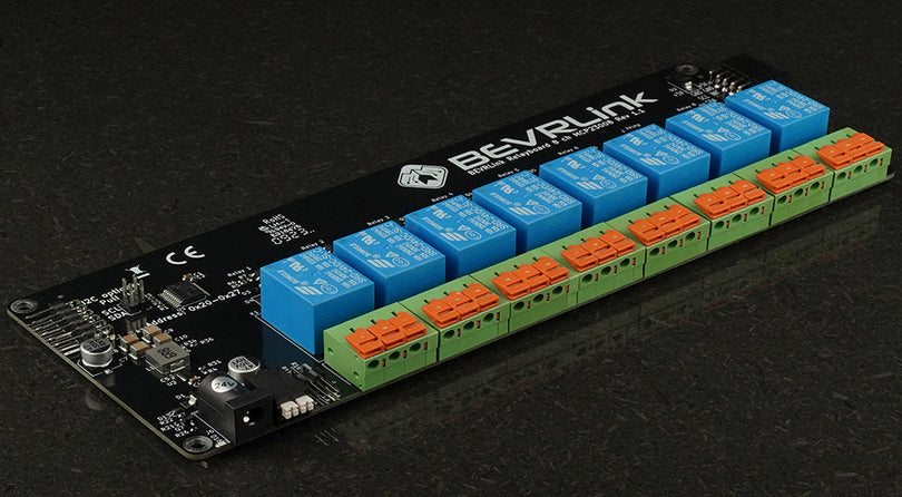
//Connected BEVRLink boards address
#define BERVLink_8_add 0x20
//Define the used pins
#define SDA 6
#define SCL 7
#define R1 10
#define R2 11
#define R3 22
#define R4 23
#define B1 18
#define B2 19
#define B3 20
#define B4 21
void setup() {
// put your setup code here, to run once:
#ifdef ALL
//i2c init, if you have an expansion connected
Wire.begin(SDA, SCL);
// Set all relays on address BERVLink_8_add as output, copy this to add another relay
Wire.beginTransmission(BERVLink_8_add);
Wire.write(0x00); // Register
Wire.write(0x00); // GPIO
Wire.endTransmission();
#endif
//Relay init if you only have relays
pinMode(R1, OUTPUT);
pinMode(R2, OUTPUT);
pinMode(R3, OUTPUT);
pinMode(R4, OUTPUT);
#if defined(RELAYnBUTTONS) || defined(ALL)
//Button init, if you have the ESP32 4+4 board
pinMode(B1, INPUT);
pinMode(B2, INPUT);
pinMode(B3, INPUT);
pinMode(B4, INPUT);
#endif
}
int relay = 1;
int val = 0;
void loop() {
// put your main code here, to run repeatedly:
#ifdef RELAYONLY
//Toggle relays
val = digitalRead(R1); // read the relay state
digitalWrite(R1, !val); // sets the Relay to the opposite of previous value
val = digitalRead(R2); // read the relay state
digitalWrite(R2, !val); // sets the Relay to the opposite of previous value
val = digitalRead(R3); // read the relay state
digitalWrite(R3, !val); // sets the Relay to the opposite of previous value
val = digitalRead(R4); // read the relay state
digitalWrite(R4, !val); // sets the Relay to the opposite of previous value
#else
//Read buttons
val = digitalRead(B1); // read the input pin
digitalWrite(R1, val); // sets the Relay to the button's value
val = digitalRead(B2); // read the input pin
digitalWrite(R2, val); // sets the Relay to the button's value
val = digitalRead(B3); // read the input pin
digitalWrite(R3, val); // sets the Relay to the button's value
val = digitalRead(B4); // read the input pin
digitalWrite(R4, val); // sets the Relay to the button's value
#endif
#ifdef ALL
Wire.beginTransmission(0x20);
Wire.write(0x0A); // Register
Wire.write(relay); // GPIO
Wire.endTransmission();
#Cycle the relay on and off
relay = (relay << 1) & 0xFF;
if (relay == 0) relay++;
#endif
delay(500);
}