


The example below is only one way how to set up the Relay Module giving examples for both with and without buttons.
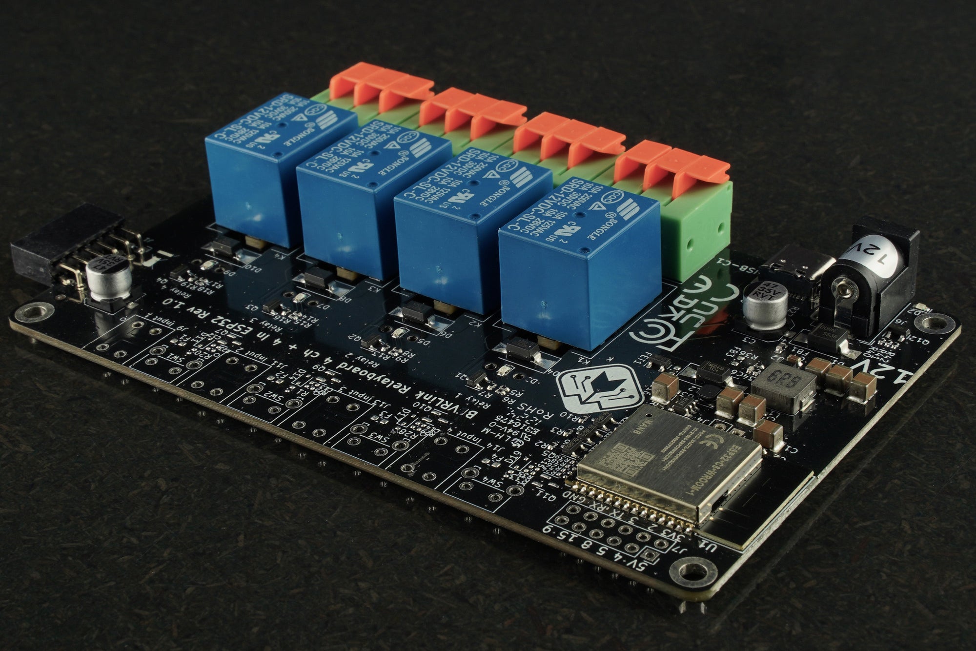
The BEVRLink Relay 4 with inbuilt ESP32 12V use the ESP32-C6 module with WiFi, Bluetooth and Zigbee/Matter support. Here we will give examples how you can control the relays with ESPHome, this can later be used in Home Assistant. With this relay module board you need the BEVRLink Power Supply 12V 2A.
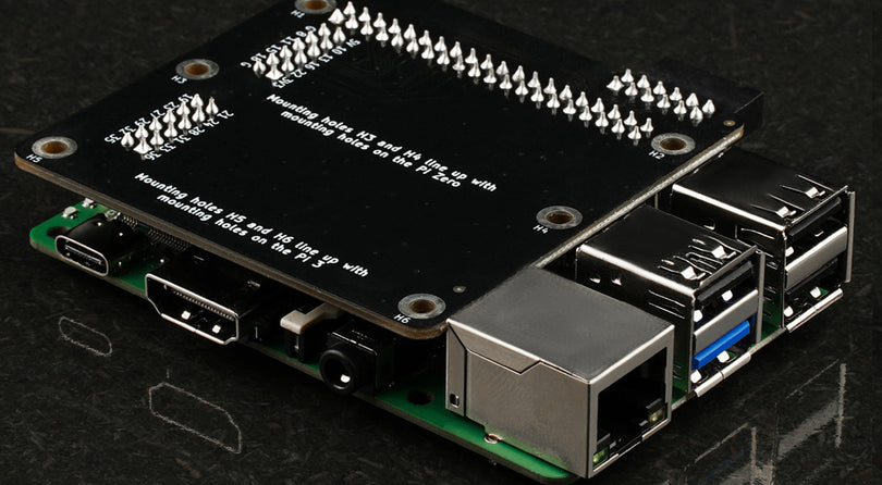
Optional for a safe setup we recommend to use case for both the manager and relay boards: BEVRLink Cases
Prerequisites
-
Install ESPHome CLI Before you can create and manage ESPHome configurations, you need to install the ESPHome Command Line Interface (CLI). This tool lets you compile firmware, run configuration wizards, and upload code to your ESP devices directly from your terminal. Here’s what you need to do:
-
Ensure Python is Installed:
ESPHome CLI requires Python 3.6 or later. Verify your Python installation by runningpython --versionorpython3 --versionin your terminal. -
Install via pip:
Open your terminal or command prompt and run:
pip install esphomeThis command downloads and installs the latest ESPHome CLI from the Python Package Index (PyPI).
-
Verify the Installation:
After installation, check that ESPHome is installed correctly by running:
esphome --versionThis should display the version number of ESPHome CLI, confirming a successful installation.
-
Note on ESP32-C6 Support:
ESP32-C6 support is currently available only through the ESPHome CLI. Other flashing tools have not yet added compatibility for the C6 module, making the CLI the recommended choice for projects involving the ESP32-C6.
-
-
Know Your Hardware
This guide assumes you’re using the BEVRLink Relay 4 board with an ESP32‑C6 module. In our examples, the relay pins are defined as:- Relay 1: GPIO10
- Relay 2: GPIO11
- Relay 3: GPIO22
- Relay 4: GPIO23
And the optional button pins (if your board version includes buttons) are:
- Button 1: GPIO18
- Button 2: GPIO19
- Button 3: GPIO20
- Button 4: GPIO21
-
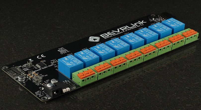
Optional – I2C Setup for Expansion
If you have additional boards connected via I2C (as shown in the original “ALL” mode), you can enable I2C with SDA on GPIO6 and SCL on GPIO7.
Creating Your ESPHome YAML
You can create a new configuration file by running:
esphome wizard bevrlink.yaml
Fill in your WiFi details and select the appropriate board (for example, if an ESP32‑C6 board option is available, use it; otherwise, use a generic ESP32 board).
After that use nano to open and edit the yaml file create by the wizard:
nano bevrlink.yaml If Arduino is used as the framework type, change to esp-idf.
ESPHome has switched to only supporting ESP32-C6 in that framework.
Example 1: Relay Only Mode
This configuration toggles all four relays every 500 ms.
esphome:
  name: bevrlink_relayonly

esp32:
  board: esp32-c6-devkitc-1
  framework:
    type: esp-idf

wifi:
  ssid: "YOUR_WIFI_SSID"
  password: "YOUR_WIFI_PASSWORD"

# Optional logging, API, and OTA updates:
logger:
api:
ota:

# If you need I2C (e.g., for additional relay expansion), uncomment the following:
# i2c:
#   sda: GPIO6
#   scl: GPIO7

switch:
  - platform: gpio
    name: "Relay 1"
    id: relay1
    pin: GPIO10
  - platform: gpio
    name: "Relay 2"
    id: relay2
    pin: GPIO11
  - platform: gpio
    name: "Relay 3"
    id: relay3
    pin: GPIO22
  - platform: gpio
    name: "Relay 4"
    id: relay4
    pin: GPIO23

interval:
  - interval: 500ms
    then:
      - switch.toggle: relay1
      - switch.toggle: relay2
      - switch.toggle: relay3
      - switch.toggle: relay4
Example 2: Relay with Buttons Mode
This configuration makes each relay follow its corresponding button. When a button is pressed, the relay turns on; when released, it turns off.
esphome:
  name: bevrlink_buttons

esp32:
  board: esp32-c6-devkitc-1
  framework:
    type: esp-idf

wifi:
  ssid: "YOUR_WIFI_SSID"
  password: "YOUR_WIFI_PASSWORD"

logger:
api:
ota:

switch:
  - platform: gpio
    name: "Relay 1"
    id: relay1
    pin: GPIO10
  - platform: gpio
    name: "Relay 2"
    id: relay2
    pin: GPIO11
  - platform: gpio
    name: "Relay 3"
    id: relay3
    pin: GPIO22
  - platform: gpio
    name: "Relay 4"
    id: relay4
    pin: GPIO23

binary_sensor:
  - platform: gpio
    name: "Button 1"
    id: button1
    pin:
      number: GPIO18
      mode: INPUT_PULLUP
    on_press:
      then:
        - switch.turn_on: relay1
    on_release:
      then:
        - switch.turn_off: relay1

  - platform: gpio
    name: "Button 2"
    id: button2
    pin:
      number: GPIO19
      mode: INPUT_PULLUP
    on_press:
      then:
        - switch.turn_on: relay2
    on_release:
      then:
        - switch.turn_off: relay2

  - platform: gpio
    name: "Button 3"
    id: button3
    pin:
      number: GPIO20
      mode: INPUT_PULLUP
    on_press:
      then:
        - switch.turn_on: relay3
    on_release:
      then:
        - switch.turn_off: relay3

  - platform: gpio
    name: "Button 4"
    id: button4
    pin:
      number: GPIO21
      mode: INPUT_PULLUP
    on_press:
      then:
        - switch.turn_on: relay4
    on_release:
      then:
        - switch.turn_off: relay4
Uploading Your Firmware
Once your YAML file is ready, use the ESPHome CLI to compile and upload the firmware:
esphome run bevrlink.yaml
This command will compile the configuration and then upload it over USB or OTA to your BEVRLink Relay 4 ch board with inbuilt ESP32.
By following this guide, you’ve adapted the Arduino code into an ESPHome configuration that can be managed via the CLI. You can further customize the configuration (for example, adding sensors, web servers, or integrations) as needed.