


The example below is only one way how to set up the Relay Module.
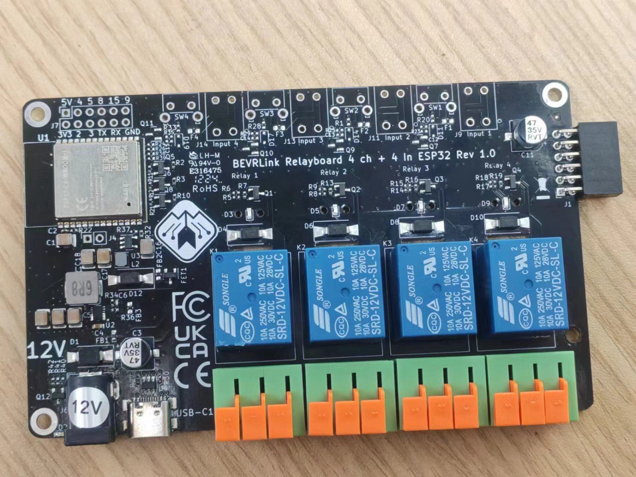
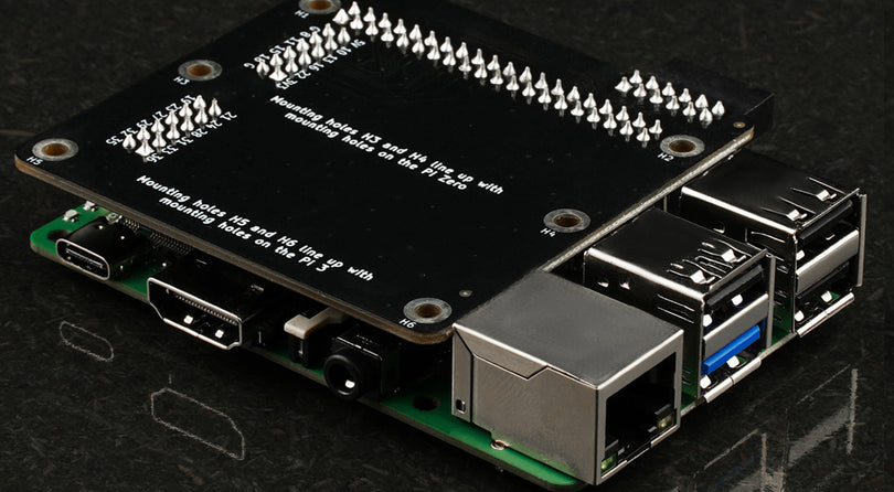
In this examples we have connected a Raspberry Pi 5 to the BEVRLink Raspberry Pi 5 8 Channel Relay 12V. With this relay module board you need the BEVRLink Power Supply 12V 2A.
This guide works for BEVRLink Raspberry Pi 5 4 Channel Relay, just omit the relay 5-8 and the status LED from the code. With this relay module you can either power the Raspberry Pi directly or back feed it from a connected BEVRLink relay Module through the Expansion Connector.
For Raspberry Pi 4 and earlier we recommend following Waveshare guide, the relay module follows the same pin mapping as their board.
Optional for a safe setup we recommend to use case for both the manager and relay boards: BEVRLink Cases
Install Raspberry Pi OS
1.

2.

3. This example uses Raspberry Pi OS Lite

4. Choose Storage

5. Set hostname, enable ssh (and WiFi credential if needed)
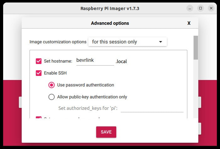
6. Press Save
7. Press Write
8.
ssh pi@bevrlink.localreplace “pi” with the user you wrote in the settings earlier, “bevrlink” with the hostname you wrote earlier.

Enable i2c (Optional, for connecting more relays boards)
9.
sudo raspi-config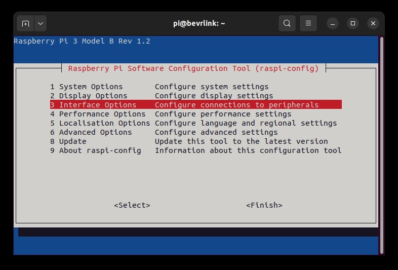
10. Select 3 Interface Options and then I5 I2C. A prompt will appear asking Would you like the ARM I2C interface to be enabled?, select Yes, press Enter, Press enter to OK and navigate down to <Finish> press Enter and reboot.
11.
sudo reboot
Install i2c and Python libraries
12.
sudo apt update
sudo apt install python3-smbus python3-dev i2c-tools
13. test if it works (optional, if more relay modules connected)
sudo i2cdetect -y 1
14. Example with chip 9554A used in 4 ch relay

nano relay.py i2c (optional, if more relay modules connected)
Each relay is a bit in the sent byte, so 0x55 converted to binary number 01010101 turns on relay 1,3,5 and 7
Remove or add lines contaning the i2c address for each relay board removed or added
# Import the GPIO library
from smbus import SMBus # Import the i2c library
from gpiozero import LED # Used to control the pins
import time # Import time library to use sleep

i2cbus = SMBus(1) # Create the i2c bus object

i2caddress_Relay_1 = 0x20 # Address of relay expansion card

# Registers
INREG = 0x09 # Input read register
OUTREG = 0x0A # Output write register
IOCONF = 0x00 # Configure IO as Input or Output register

# Config all pins as outputs
i2cbus.write_byte_data(i2caddress_Relay_1, IOCONF, 0x00)

# Initialize the on board relays
status_LED = LED(12)
relay_1 = LED(5)
relay_2 = LED(6)
relay_3 = LED(13)
relay_4 = LED(16)
relay_5 = LED(19)
relay_6 = LED(20)
relay_7 = LED(21)
relay_8 = LED(26)
status_LED = LED(12)

while (True): # Loop
    # Turn on half the relays
    i2cbus.write_byte_data(i2caddress_Relay_1, OUTREG, 0x55)
    relay_1.on()
    relay_2.off()
    relay_3.on()
    relay_4.off()
    relay_5.on()
    relay_6.off()
    relay_7.on()
    relay_8.off()
    status_LED.on()
    time.sleep(1) # Wait 1 second
    # Turn on the other half
    i2cbus.write_byte_data(i2caddress_Relay_1, OUTREG, 0xAA)
    relay_1.off()
    relay_2.on()
    relay_3.off()
    relay_4.on()
    relay_5.off()
    relay_6.on()
    relay_7.off()
    relay_8.on()
    status_LED.off()
    time.sleep(1) # Wait 1 second
python relay.py
15. CTRL+C to stop script